Introduction
In Belgium, Elia, as the transmission system operator (TSO), is responsible for transporting electricity at high voltage (30 kV – 380 kV) and for maintaining the associated infrastructure. This infrastructure consists of various components. According to Elia [1], the company operates more than 800 high-voltage substations, 22.000 pylons, 5.500 km of overhead lines, and 3.000 km of underground cables. As a result, this infrastructure is a visible part of the landscape almost everywhere.
Electrification plays a crucial role in the energy transition, and the demand for electricity is expected to increase significantly in the coming years. Elia forecasts an annual increase of 3,7% between 2024 and 2034, from 82,9 TWh to 132,9 TWh, meaning that demand in 2034 will be about 60% higher than in 2024. In the medium and long term, reinforcements and extensions of the transmission grid are therefore inevitable. According to the same study [2], nearly 3 GW of additional transmission capacity will already be required by 2029.
There are two ways to increase the active electrical power (P = U ∗ I): either by raising the voltage or by increasing the current. If the network voltage were to change, all installations (transformers, converters, insulators, …) would need to be adapted to the new voltage. This would be an enormously costly adjustment and is therefore highly undesirable. To transmit more power at the same voltage, the current must be increased. Many existing overhead lines cannot cope with these higher currents as they risk overheating, expanding, and sagging too low [1]. Underground cables are not always suitable for increased currents either, as the generated heat cannot always be sufficiently dissipated [3]. For this reason, Elia is carrying out various projects to replace high-voltage cables, both overhead and underground. But how does such a project actually proceed? And which cable technologies are suitable?
Replacement of Overhead Lines
At present, several projects are underway to replace existing overhead lines. One example is the 380 kV line between the high-voltage substations Mercator in Kruibeke and Bruegel in Dilbeek [1]. For the replacement, new HTLS (High Temperature, Low Sag) conductors are being installed. Owing to their composition, these conductors are less prone to sagging as a result of the heat generated during electricity transmission. Because the new conductors are heavier than the old ones, the foundations of all seventy pylons must be reinforced, and six pylons have to be replaced entirely.
The replacement of overhead lines involves various challenges and follows a precise procedure. First, Elia installs temporary wooden protection portals at points where the route crosses obstacles such as houses, roads, or railways [4]. These portals ensure that the conductors remain at a safe height during the works, even if they temporarily sag too far [1].
Next, running blocks are attached to each arm of a high-voltage pylon, allowing the conductors to be pulled smoothly across the pylons. Afterwards, the spacers and insulators of the old conductors are removed. To ensure safe working conditions, the overhead line is divided into several sections, so that the conductors can be replaced one by one [1].
Both the old and the new conductors are then attached to pulling ropes so that, with the aid of winches and braking machines, the new conductors can be drawn directly onto the pylons while the old ones are wound up. This method makes the replacement process highly efficient [5]. Finally, the new insulators and spacers are installed.
Because the new conductors are heavier than the previous ones, it is sometimes necessary to replace entire pylons. In order to maintain supply security during the works, Elia installs temporary pylons while an existing one is being dismantled. As a result, three pylons may temporarily stand at a single location [1].
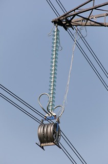
Figure 1: Running Blocks with Insulator [6]
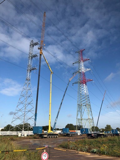
Figure 2: Temporary Pylon [7]
Replacement of Underground Cables
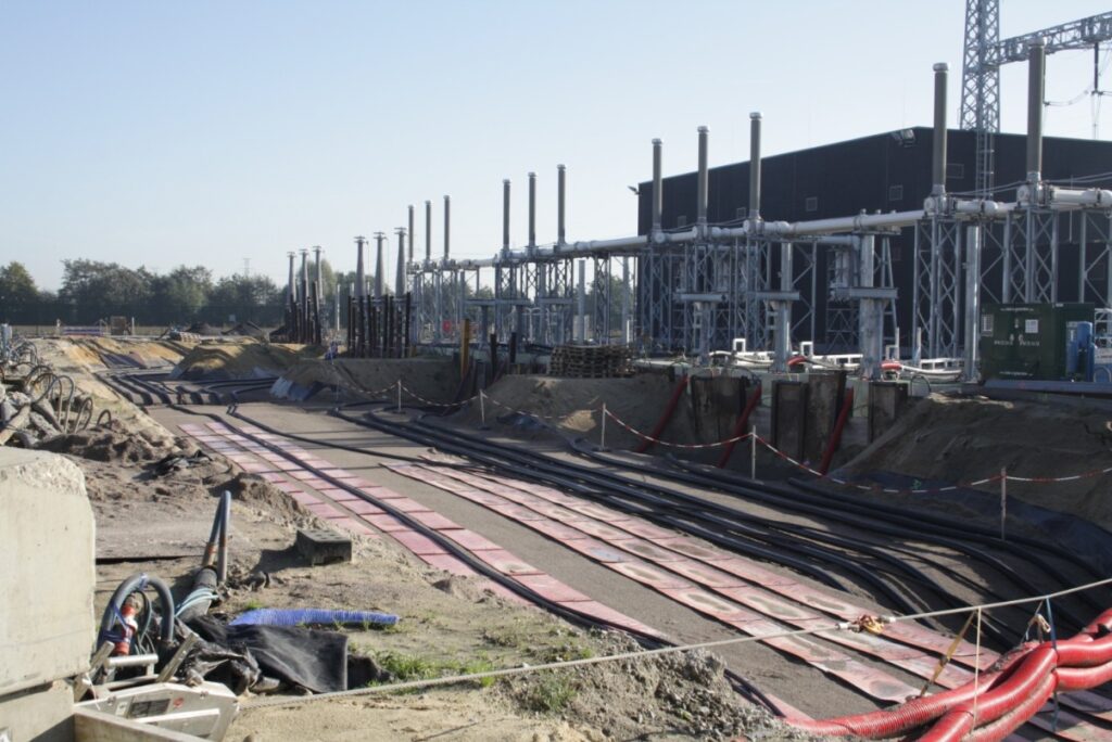
AC underground cables are commonly installed in one of three configurations: as a bundled three-phase cable, as three separate cables arranged in a triangular formation, or as three individual cables laid flat side by side. The flat configuration offers a key operational advantage, as the magnetic fields of the individual cables interfere less with one another. In addition, cables that are spaced slightly apart can dissipate heat more efficiently [8]. Consequently, the flat arrangement is generally preferred.
Underground cables occasionally need to be replaced. The most commonly used method for this purpose is open-trench excavation. For each section, a trench of approximately two metres deep and six to twelve metres wide is excavated to allow the new cables to be installed in a flat configuration [9]. This method offers additional advantages, including technical simplicity and the possibility of implementing soil improvement measures. Since not all soil types conduct heat equally well, using backfill material with high thermal conductivity allows the cables to dissipate heat more effectively, thereby enhancing their current-carrying capacity [8].
However, this technique also presents several significant disadvantages. Excavation has a considerable impact on the landscape and requires a large working area. In addition to the trench itself, space is needed for the temporary storage of excavated soil and for the movement of construction machinery. The method is also material- and time-intensive, and it can cause substantial disruption in densely populated or frequently used areas. When a trench crosses agricultural land, that land cannot be used for cultivation during the construction period, requiring compensation to the landowner. Such negotiations further increase both project duration and cost [8].
Despite the operational advantages of open-trench excavation once the cable is in service, the disruption it causes drives the search for alternative methods. In 2010, new cables were still installed via excavation in 90% of cases, whereas by 2020, excavation was used for only around half of new installations [8].
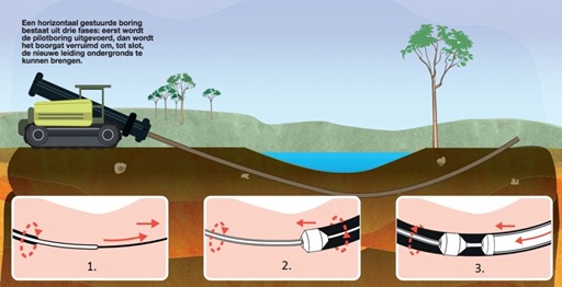
Today, guided drilling has emerged as a competitive alternative to open-trench excavation [8]. This is a trenchless technique that is increasingly used for underground infrastructure, including electrical lines. The process takes place in three stages. First, a pilot bore is conducted using a small, asymmetric drill head that creates a narrow tunnel. By locking certain parts of the head, it can be accurately steered thanks to its asymmetric shape. Next, the tunnel is enlarged, and finally, the cables are pulled through the bored tunnel [10]. Figure 4 illustrates this process.
Cable Technology
For decades, aluminium conductors with steel reinforcement (ACSR) have been the standard in transmission networks. These cables consist of a central steel core, wrapped with one or more layers of aluminium conductors. Aluminium provides low mass and high electrical conductivity, while the steel core increases mechanical strength and, due to its corrosion resistance, extends the service life of the line [12].
A significant disadvantage of ACSR lines, however, is that they expand considerably at higher temperatures, typically above approximately 100°C. This causes the conductors to sag, which can be problematic for the pylons and for objects beneath the line. To mitigate this, HTLS (High Temperature, Low Sag) cables are increasingly being used. These cables have a core made of materials with high thermal resistance and tensile strength, such as carbon fibre or specialised alloys. The outer conductors are made of an aluminium alloy capable of withstanding higher temperatures. Thanks to these properties, HTLS cables can operate safely at elevated temperatures, allowing them to carry more current and therefore provide a substantially higher load capacity than conventional ACSR cables [12].
Conclusion
Strengthening the transmission network is a crucial prerequisite for enabling the energy transition. Growing electrification and rising power demand require a robust infrastructure capable of safely and efficiently transporting large amounts of electricity. The replacement of existing overhead lines and underground cables forms an essential part of this effort.
New HTLS conductors allow higher power transfer at elevated temperatures without adverse effects on the infrastructure. For underground cables, techniques such as open-trench excavation and guided drilling each offer their own advantages and limitations, but together they provide the necessary flexibility for network renewal.
In the coming years, the challenge will be to implement these upgrades on a large scale and in a timely manner, taking into account both technical feasibility and societal impact. Only by doing so can the transmission network be made sufficiently future-proof to support the energy transition, ensuring that the often-invisible backbone of our electricity system continues to meet the growing demand.